In the ecosystem of Computer Numerical Control (CNC) machining, the interface between the operator and the machine is often the most overlooked yet most physically stressed component
In the ecosystem of Computer Numerical Control (CNC) machining, the interface between the operator and the machine is often the most overlooked yet most physically stressed component. The
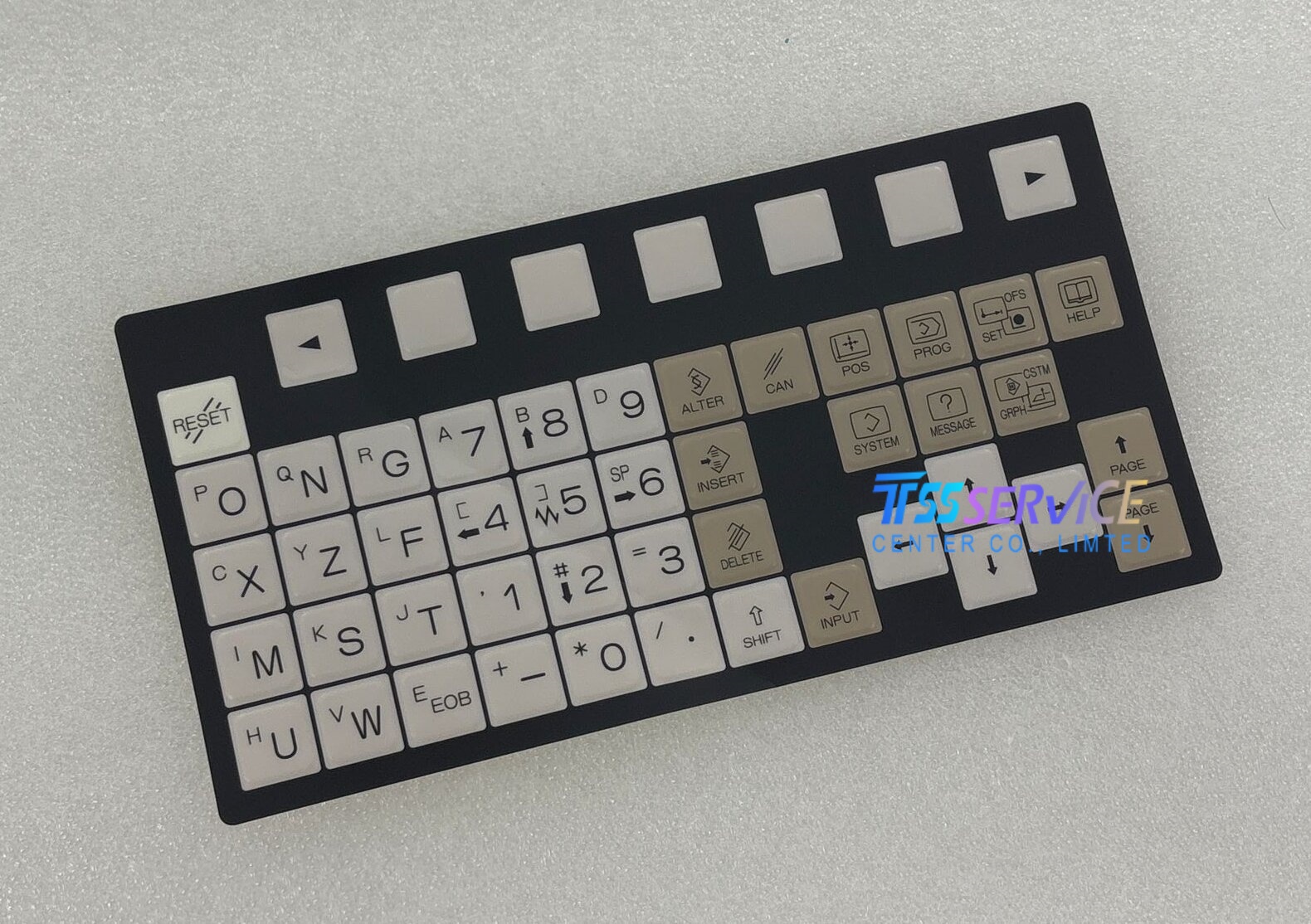
A02B-0319-K711 membrane keypad film is not merely a replacement part; it is a precision-engineered consumable designed specifically for the
FANUC 0i-MF,
0i-TD, and
0i-MD series controllers. These controllers are the backbone of countless milling machines, lathes, and multi-axis machining centers. This article provides a deep technical analysis of this keypad film, focusing on its construction, failure modes, installation methodologies, and why it remains a mission-critical component for maintaining production uptime.
1. The Technical Architecture of the Membrane Keypad Film
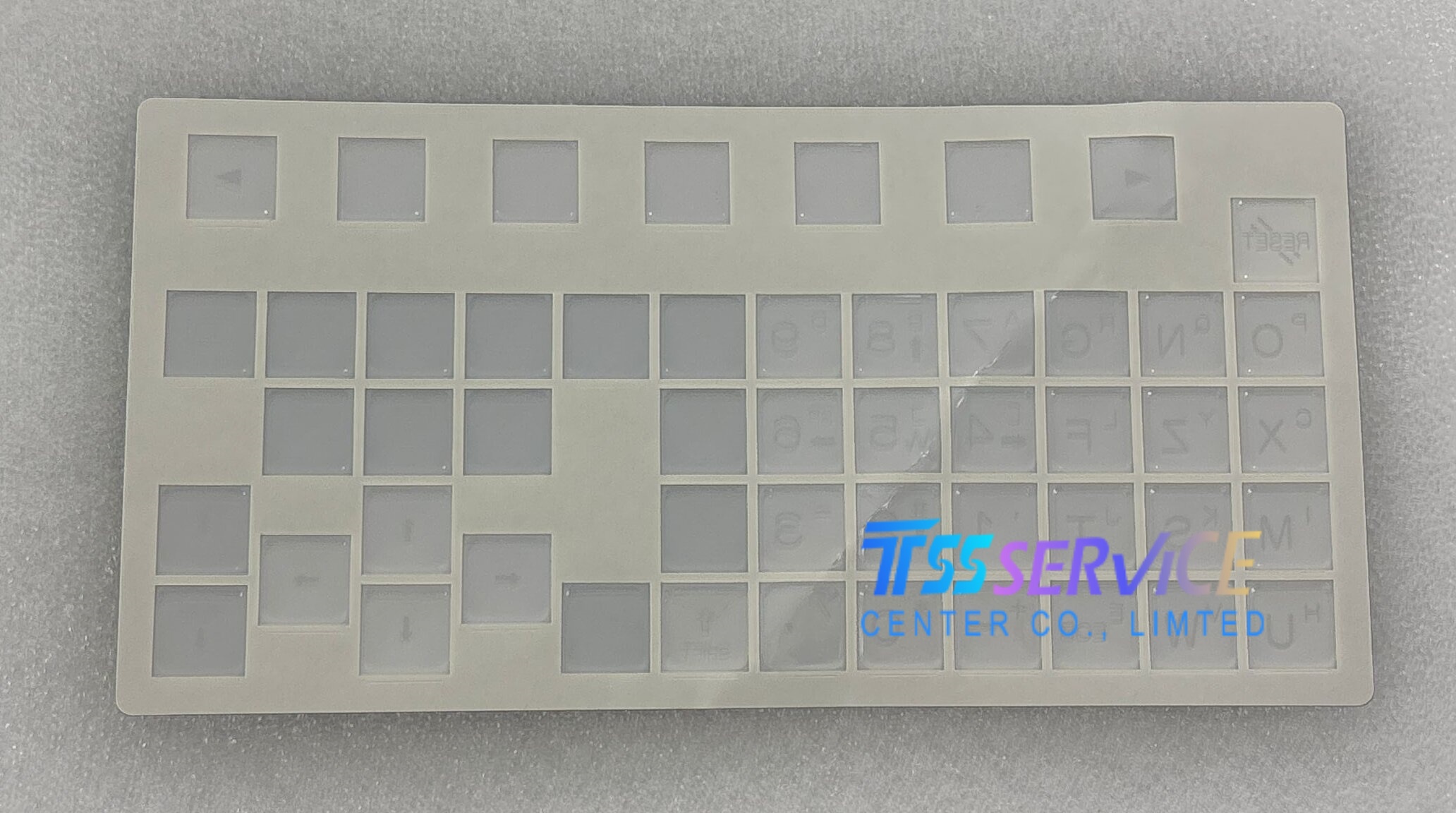
Contrary to common perception, a membrane keypad is not simply a sticker with buttons. The
A02B-0319-K711 is a multi-layer, laminated structure designed for high-cycle industrial use. Understanding its architecture is essential for diagnosing failures.
-
Graphic Overlay Layer (Top Polycarbonate): This outer layer is engineered from hard-coated polycarbonate specifically chosen for its resistance to cutting fluids, oils, and common industrial solvents like isopropyl alcohol. It is this layer that carries the legends, key boundaries, and color coding. Unlike generic overlays, the FANUC specification for this film mandates a specific abrasion resistance (typically meeting ASTM D1044 standards for Taber abrasion) to prevent the legends from rubbing off after months of constant contact.
-
Spacer Layer (Adhesive Gasket): A precision-cut polyester spacer provides the critical "snap" or tactile feedback. This layer determines the air gap distance between the top circuit and the bottom circuit. If this spacer degrades or delaminates, the keys will become mushy or unresponsive. The A02B-0319-K711 uses a high-tack, temperature-stable adhesive that withstands the heat generated by the FANUC display backlighting.
-
Lower Circuit Layer (Silver Ink Circuitry): This is the functional heart of the film. Conductive traces are printed using silver-infused polymer thick film (PTF). The FANUC 0i-MF series, in particular, uses a matrix scanning method to read key presses. The A02B-0319-K711 circuit layout is precisely aligned to the controller's ribbon cable pin-out. Any micro-crack in these silver traces—often caused by repetitive flexing—will result in either a dead row of keys or a phantom key press.
-
Rear Adhesive Layer: The mounting adhesive is not standard double-sided tape. It is a closed-cell foam acrylic adhesive that serves two purposes: it bonds the film to the control panel bezel, and it provides a vibration-dampening barrier. A failure in this layer (lifting at corners) allows coolant ingress, which destroys the circuits below.
2. Critical Compatibility Across FANUC Series: 0i-MF, 0i-TD, and 0i-MD
While these three controller families share a common physical panel layout, their electrical logic is not identical. The A02B-0319-K711 is specifically engineered to bridge these differences.
-
FANUC 0i-MF (Milling): This series requires a specific membrane layout that includes dedicated keys for tool offset management and graphic display toggling. The keypad film ensures that the capacitive load of the silver circuits matches the MF's scanning frequency. Using a non-MF specific film on this controller can cause key ghosting where pressing one key inadvertently registers a second key.
-
FANUC 0i-TD (Turning): The TD variant features a distinct layout for spindle speed override and manual tailstock control. The A02B-0319-K711 incorporates these specific contact points without altering the ribbon connector interface.
-
FANUC 0i-MD (Multi-purpose): The MD series is a hybrid. The keypad film must be robust enough to handle both milling and turning operations, often in high-vibration environments like dual-spindle lathes.
3. Common Failure Modes and Diagnostic Protocol
Before ordering a replacement, operators must differentiate between a failed keypad film and a failed controller board. This section outlines a diagnostic protocol specific to the A02B-0319-K711.
-
Failure Mode A: Non-responsive Key Cluster. If a specific row or column of keys (e.g., all keys in the numeric pad) fails, this indicates a cracked silver trace at the flex tail. The flex tail is the thin strip that bends 90 degrees to plug into the main board. This is the #1 mechanical failure point. Solution: Replacement of the film.
-
Failure Mode B: Sporadic Key Activation or "Stuck" Key. This is often caused by contamination ingress. Coolant or cutting oil seeps under the graphic overlay and creates a conductive path between two circuits. The A02B-0319-K711 has a raised seal around the connector to prevent this, but if the top layer is punctured or worn, the seal fails. Solution: Replace the film and inspect the gasket seal on the controller housing.
-
Failure Mode C: Tactile Loss. If the keys feel "dead" or require excessive force, the polyester dome spacer has collapsed. This is a typical consequence of UV exposure over 3-5 years. Solution: Replacement, as the spacer cannot be reconditioned.
4. Installation Best Practices for Longevity
A membrane keypad is a consumable item. However, improper installation can reduce its lifespan from a typical 1-2 million actuations to just a few months. Follow these steps grounded in industrial maintenance best practices.
-
Surface Preparation: The mounting surface on the FANUC control panel must be perfectly clean. Use isopropyl alcohol (99% concentration) and a lint-free wipe. Avoid acetone or MEK, as these can cloud the polycarbonate window on the film or attack the underlying plastic bezel.
-
Alignment and Tack: The A02B-0319-K711 has alignment lugs specific to the FANUC 0i bezel. Do not force the film. Align the ribbon connector first to ensure the tail reaches the socket without stretching.
-
Connector Seating: The ribbon cable must be inserted straight into the ZIF (Zero Insertion Force) connector on the main board. Do not use metal tools to push the cable; use a plastic spudger. Improper seating will cause intermittent failures that mimic a dead keypad.
-
Burn-in Cycle: After installation, allow the adhesive to cure for 12 hours before exposing the machine to heavy coolant flow. The acrylic adhesive reaches its full bond strength after 24 hours at 20°C (68°F).
5. Why the "Genuine vs. Third-Party" Discussion Matters
As an SEO and industry expert, I must address the critical distinction between genuine FANUC A02B-0319-K711 films and third-party alternatives. While the original FANUC product carries a higher price point, it adheres to stringent RoHS and electrical safety certifications that third-party films often fail to meet.
-
Silver Ink Purity: Genuine FANUC films use silver ink with 75-80% silver content. Third-party films often reduce this to 60% to cut costs, resulting in higher electrical resistance and slower signal transmission. In a high-speed CNC loop, this latency can cause the controller to miss a key press during critical manual jogging operations.
-
UV Stability: The polycarbonate overlay on the genuine film is UV-stabilized for a 5-7 year industrial lifespan. Third-party films often yellow and become brittle after 18 months of exposure to shop lighting and sunlight.
-
EMI Shielding: The A02B-0319-K711 incorporates a thin EMI shielding layer (typically a carbon-loaded film) that prevents electrical noise from the servo drives and spindle motors from interfering with the keypad signals. Many aftermarket films lack this, leading to erratic behavior in high-EMI environments.
Conclusion
The
A02B-0319-K711 membrane keypad film is a deceptively complex component that acts as the sole bridge between the operator and the FANUC control system. For shop floors running 0i-MF, 0i-TD, or 0i-MD controllers, recognizing the signs of mechanical fatigue—tactile loss, key ghosting, or coolant ingress—is essential for proactive maintenance. Investing in the genuine component ensures that the silver circuitry, EMI shielding, and adhesive construction meet the demanding thermal and chemical conditions of high-volume machining. When installing, prioritize surface cleaning and gentle connector handling to maximize the lifespan of the replacement. Treat this interface not as a sticker, but as a piece of precision electromechanical equipment that directly influences your machine's reliability and your operator's efficiency.


