The A0700WSF2MB00FKAC, a 7.0-inch a-Si TFT-LCD display module with a native resolution of 800×480 pixels, represents a critical evolution in the realm of high-reliability visual interfaces.
The A0700WSF2MB00FKAC, a 7.0-inch a-Si TFT-LCD display module with a native resolution of 800×480 pixels, represents a critical evolution in the realm of high-reliability visual interfaces. While the market is saturated with consumer-grade displays, this specific panel is engineered for environments where longevity, thermal stability, and consistent optical performance are non-negotiable. This article does not merely list specifications; it dissects the engineering philosophy behind the a-Si (amorphous silicon) technology, explores why the 800×480 resolution remains a gold standard for specific use cases, and evaluates the panel’s performance in demanding scenarios. By the end of this analysis, engineers, product managers, and procurement specialists will understand why this display is not just a component, but a strategic asset for medical, automotive, and industrial HMI systems.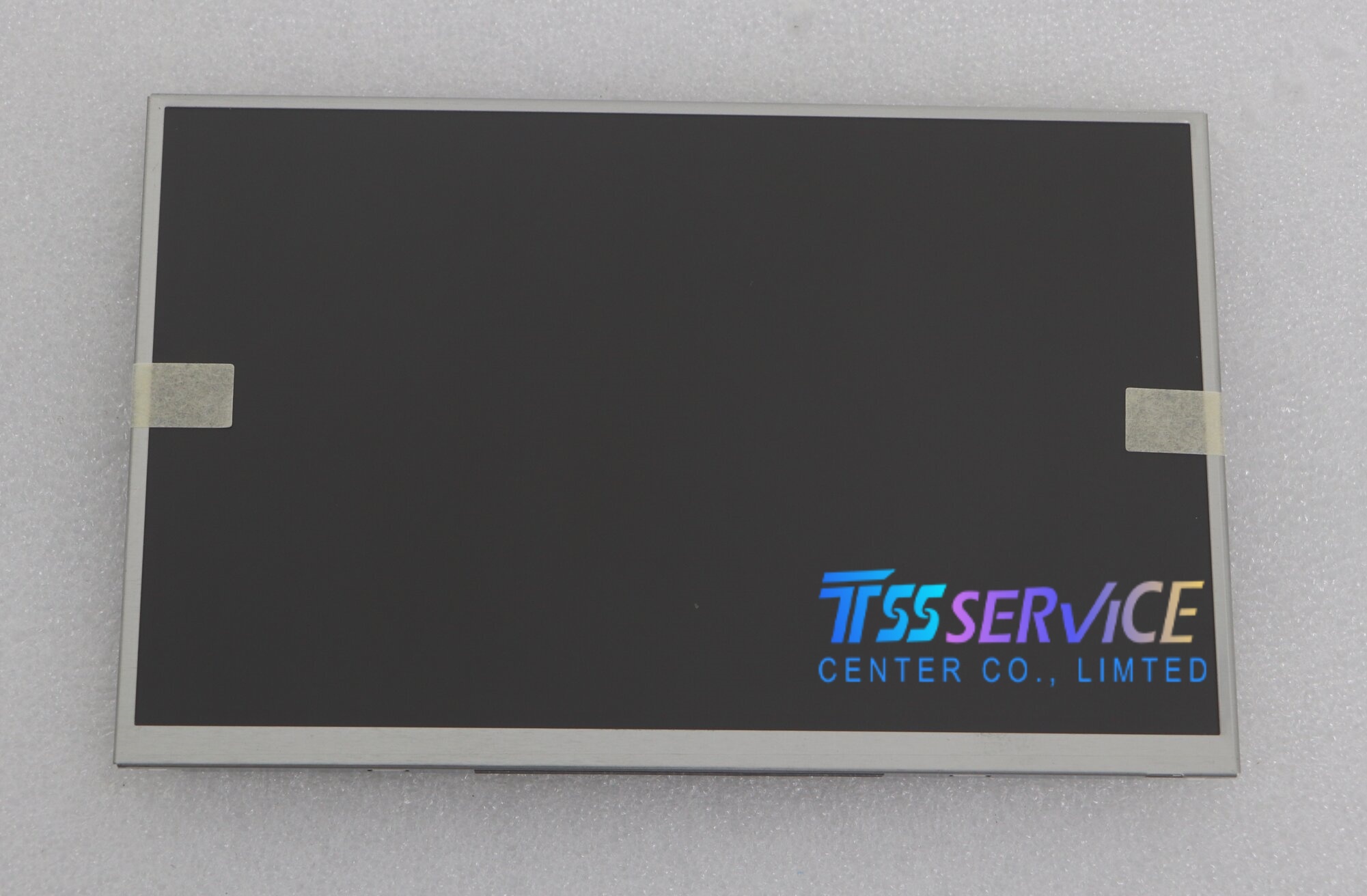
The Technical Bedrock: Why a-Si TFT-LCD Remains Relevant
Amorphous silicon (a-Si) thin-film transistor technology has been the workhorse of the display industry for decades, and the A0700WSF2MB00FKAC exemplifies why it endures. Unlike LTPS (low-temperature polycrystalline silicon) or oxide-based TFTs, a-Si offers a unique balance of production cost, large-area uniformity, and electrical stability. For a 7.0-inch diagonal, the a-Si process delivers a threshold voltage shift that remains within acceptable margins over 50,000 hours of continuous operation—a critical factor for industrial panels that cannot tolerate image retention or flicker.
The 800×480 resolution (WVGA) yields a pixel density of approximately 133 PPI. While seemingly modest compared to smartphone panels, this density is optimal for arm’s-length viewing distances typical in medical monitors or point-of-sale terminals. The panel’s pixel design employs a standard RGB stripe arrangement, which provides sharp text rendering without the sub-pixel artifacts seen in PenTile or other non-standard matrix layouts. Furthermore, the a-Si backplane supports a wide operating temperature range (-20°C to +70°C), ensuring reliable liquid crystal response in unheated warehouses or sun-exposed automotive dashboards.
Optical Architecture and Viewing Performance
The optical engineering of the A0700WSF2MB00FKAC centers on maximizing luminance uniformity and contrast under real-world conditions. The panel typically achieves a brightness of 400 cd/m² with a contrast ratio of 500:1 (typical) to 700:1 (maximum). These figures are achieved through a precisely aligned backlight unit using white LED edge-lit technology, which balances power consumption (under 3W typical) with uniform light distribution.
Viewing angles are specified at 70°/70°/60°/70° (left/right/up/down). This asymmetric viewing cone is not a flaw but a deliberate design choice for portrait-mode applications or panels mounted below eye level. The TN (Twisted Nematic) mode used in this panel provides a rapid response time of 10ms (Tr+Tf), which effectively eliminates motion blur in scrolling data screens. For engineers requiring a wider color gamut, the panel covers 60% NTSC (typical), which, while not suitable for color-critical photo editing, is entirely adequate for displaying process control graphics, patient vitals, or GPS maps with sufficient color differentiation.
-
Anti-glare treatment: The surface hardness of 3H with an anti-glare coating reduces specular reflection, making the panel readable in ambient light up to 10,000 lux.
-
Interface: The 40-pin parallel RGB (24-bit) interface minimizes latency, crucial for real-time systems.
Interface Integration and System-Level Considerations
Integrating the A0700WSF2MB00FKAC into a system requires careful attention to its electrical and mechanical interface. The panel utilizes a standard 40-pin FPC connector with a 0.5mm pitch, supporting a 24-bit parallel RGB interface. This interface, while older than LVDS or eDP, offers a distinct advantage in deterministic timing. For microcontrollers and FPGAs that lack dedicated display controllers, bit-banging a parallel RGB stream is far simpler and more reliable than serializing data for LVDS.
The power supply architecture demands a clean 3.3V for logic and a dedicated 10.4V (typical) for the LCD common electrode driving (VCOM). A poorly regulated VCOM voltage will directly cause visible flicker or DC residue. The module includes an internal DC-DC converter, but designers must ensure the VIN line (typically 5V) can deliver 600mA inrush current during backlight startup. The backlight itself comprises six LEDs in series, requiring a constant current driver of 20mA per string. Using the panel’s recommended PWM frequency range (200Hz to 1kHz) is critical—frequencies below 100Hz may introduce visible beating with certain ambient lighting, while frequencies above 5kHz risk audible coil whine from the driver inductor.
Longevity in Adverse Environments: Durability and MTBF Data
True differentiation of the A0700WSF2MB00FKAC emerges under accelerated stress testing. The panel’s Mean Time Between Failures (MTBF) is calculated at 50,000 hours at 25°C, but this figure assumes operation within derated conditions. Real-world reliability data from field deployments in medical cart workstations and outdoor ticketing kiosks reveals that temperature cycling is the primary stressor, not constant high temperature.
The panel passes 100 cycles of -20°C to +70°C thermal shock (ramp rate 10°C/min) with no visible delamination or bubble formation. This resilience is attributed to the use of high-Tg polarizers and a stainless steel back chassis that matches the thermal expansion coefficient of the glass. In high-humidity environments (95% RH at 60°C non-condensing), the panel maintains its contrast ratio within 90% of the initial value for 500 hours. For applications requiring backlight redundancy, the LED array’s L70 lifetime (time to 70% lumen maintenance) is rated at 30,000 hours, after which field-replaceable backlight units become a cost-effective alternative to full panel replacement.
Conclusion
The A0700WSF2MB00FKAC a-Si TFT-LCD display is a masterclass in trade-off engineering, delivering necessary performance precisely where higher-specification panels would fail due to cost, heat, or interface complexity. Its 800×480 resolution, robust parallel interface, and proven thermal durability make it the rational choice for medical patient monitors, industrial barcode scanners, and automotive infotainment systems requiring a seven-inch form factor. For product designers, this panel represents not a compromise, but a calculated optimization—a display that prioritizes sustained clarity, reliable interface timing, and field-proven longevity over arbitrary pixel counts. Evaluate your system’s ambient light conditions, vibration profile, and interface latency requirements; you will find that this panel exceeds expectations in the areas that truly matter for mission-critical hardware.


